This is a guest post by Michele Mattix of Geomattix, LLC.
CAD users beware! While ArcGIS supports the mapping of CAD data, ArcPad – ESRI’s field software – does not. Though it is no problem to convert CAD data into the geodatabase format, the handling of CAD annotation can present challenges. In this article, I will walk you through a problem one of my clients was having and the solution I came up with.
Background
My client has a Trimble GeoXH GPS unit on which they use ArcPad to collect field data. I was contacted to help them clean up their GIS data. In addition to maintaining GIS data, they also had several CAD files. They wanted to consolidate all of the data into one efficient geodatabase. I designed and created a new geodatabase for them and converted/imported the CAD data into it. Among the CAD data were very detailed roads data that my client wanted to use as background data in ArcPad. In CAD format, the roads were stored as lines and the road names were stored in a CAD annotation feature class. When I converted the CAD data into the geodatabase format, two feature classes were created: Roads – which contains the line data, and Roads_Annotation – a point feature class that contains the road names. See the figure below.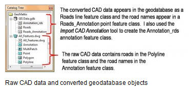
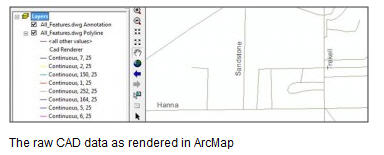
When viewed in ArcMap, the raw CAD Polyline (roads) and Annotation layers appear as roads with labels, see below. My client wanted to reproduce this same look with the geodatabase data.
Using the newly created geodatabase Roads_Annotation layer – which contains point data with road names as attributes — overwhelms the map with unnecessary points. Also, the labels will not necessarily be oriented along the roads, as show below.
It would be nice to use the road names from the Roads_Annotation layer as labels in the Roads layer. I could accomplish this by joining the two tables if only there were a key field. Alas, there is not.
There is an Import CAD Annotation tool available in ArcToolbox that will convert a CAD annotation feature class into a geodatabase annotation feature class. The annotation will look exactly as it does in the raw CAD data. I used this tool to create the Annotation_rds feature class that works great in ArcMap. ArcPad, however, does not support annotation feature classes.
The Problem
My client wanted both the roads and the road names to appear in ArcPad. With no other options, I needed to find a way to use the Roads_Annotation point feature class to label the roads properly.
The Solution
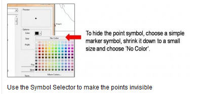
Here’s how I made the Roads_Annotation point layer mimic the raw CAD annotation. First, I symbolized the points so that they do not appear on the map. I did this by choosing a basic ESRI point symbol that does not contain an outline, such as Circle 1, and then shrinking the size down to 7 points – any small size will work. In the color palette selector, I chose “no color”, see below.
The effect is that the points do not appear even though the layer is turned on.
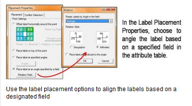
Next, I needed to make the labels orient with the roads. Upon inspection, I discovered that the Roads_Annotation feature class contains an attribute field called TxtAngle. The values range between 0 and 90 and represent the orientation angle of the original CAD annotation.
The default behavior for labels of point features in ArcMap is for the labels to be placed horizontally at a designated location around the point. This works for point data, but not for my line data. Fortunately, the default behavior can be changed. From the labels tab in the layer properties, I chose the option to place the labels at an angle specified by a field in the table. This allows ArcMap to position the labels as they were originally designed in CAD, see below.
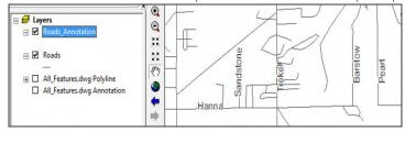
Voila! I now have labeled roads, see below. The label font, color, and size can be adjusted to match the CAD annotation, see below.
Now when my client checks data out for use in ArcPad, the Roads and Roads_Annotation layers both can be checked out as reference data. This is an easy way to provide a light-weight and detailed labeled roads layer in ArcPad.

