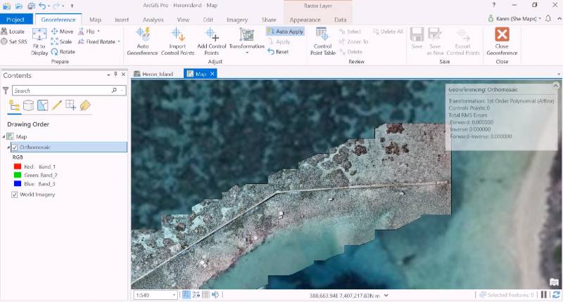
ArcGIS Pro enables the creation of Ground Control Points as a way to georeference drone data to satellite base map data, so that user-generated imagery data is placed on the correct spatial location and fit for further use inside a GIS.
When bringing in a new drone imagery dataset into ArcGIS Pro, it needs to be checked for accuracy and consistency and changed if necessary. Because onboard GPS of a drone isn’t as accurate as preferred, the resulting orthomosaics aren’t necessarily in the right location. One way of doing visual inspection of how the data lines up with existing base map data, is by using the swipe tool at the Appearance tab for a quick check to see how well data align with satellite imagery base map data. However, the right way to place the data in the right location is to apply georeferencing, which is the process of defining the location of an image using map coordinates and assign the coordinate system of the map frame to the image. Georeferencing an image allows it to be viewed, queried, and analyzed with other geographic data.
Using Manual and Digital Ground Control Points (GCPs)
Often, the imagery captured shows a set of physical ground control points that have been placed in the field before capturing aerial imagery. Their positions are known to the user because a GPS has been used to locate them. After image capture, these GCPs can be used to find the right locations for the imagery data and line them up correctly inside a GIS. However, if physical GCPs aren’t available, there are georeferencing tools available in ArcGIS Pro to tag an unknown data source to a known image source so that its coordinates match up.
To start georeferencing drone imagery inside of Pro, head over to the Imagery tab, that includes a Georeference tool for a selected raster layer. Clicking the tool brings up a new menu with multiple georeferencing tools. One menu items allows you to add multiple digital GCPs in the drone orthomosaics, for example in features that are visible in both images. This tool asks you to first click on a location in the source layer that is being georeferenced (in this case, the drone data), and next by clicking at the corresponding location on the reference layer (the satellite image base map).
After clicking on a location in the orthomosaic, a point is visible on the map. To find the same location on the basemap, you can untick the orthomosaic in the map contents window on the left, so that it isn’t displayed anymore inside the map. This enables you to mark the same feature in the basemap layer. As a result of adding these ground control points, the orthomosiac will be shifted when it is made visible in the map window again. Ideally, a good distribution of ground control points is found throughout the orthomosiac, so that the image is aligned with the image it is being georeferenced to.
Attribute data of the GCPs
All added GCPs are saved into an attribute table that contains the source x and y coordinates of both images, as well as the variance for each point, which shows how accurate the model is (the lower the residuals, the more accurate it is). It’s possible to show how the orthomosaic shifts in relation to the underlying basemap by unselecting or deleting one or more GCPs from the attribute table and the corresponding map. The attribute table enables you to select which raster transformation to use: the transformations you’ll be able to use depends on how many GCPs are created (more GCPs means more transformation options). Luckily, drone orthomosaics are often no more than a few meters off from their real location and using the 1st order polynomial (affine) transformation will do the job to georeferenced the data correctly.
To continue and use the same GCPs in the future, you can choose to export your GCPs to a file using the Export Ground Control Points tool on the right of the Georeference menu. You can save the transformed image as a new image by clicking the “Save as New” icon in the same menu. Now, an Export Raster menu opens on the right of the screen, where you can specify the name and location of the output raster dataset, a coordinate system and other output defaults. To finish the process, clicking the “Export” button will create the new raster file on the specified location.
Sources:
Learn how to georeference your data in ArcGIS Pro, Karen Joyce

