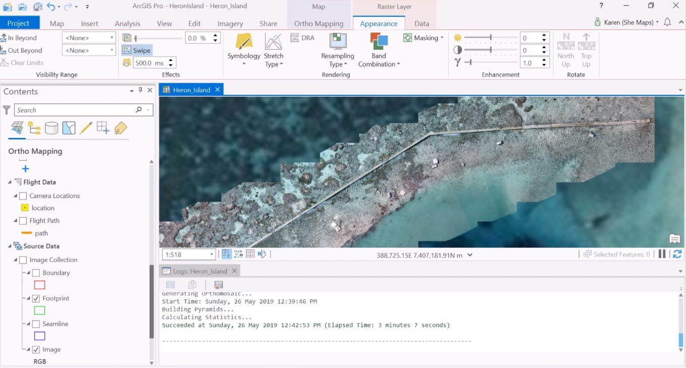
ArcGIS Pro provides an ortho mapping workflow for creating orthomosaics from geotagged drone imagery.
What are orthomosaics and orthorectification?
An orthomosaic is a georeferenced image product mosaicked from an image collection, where the geometric distortion of the individual images has been corrected by orthorectification. Orthorectification is a process by which imagery is geometrically corrected so that coordinates in the images accurately represent coordinates on the ground. ArcGIS Pro provides an image workflow for creating orthomosaics through the automated process of orthorectification. An input dataset of multiple (aerial or satellite) images are stitched together, geometrically corrected and georeferenced so they can be placed on a map.
Creating a New Ortho Mapping Workspace with ArcGIS Pro
A new orthomosaic workflow starts with creating a new project in ArcGIS Pro. Next, head over to the Imagery tab on the ribbon interface and click “New Workspace”, which will start a new ortho mapping workspace that is saved within the current project. On the left of the screen, a new configuration menu opens up, titled “New Ortho Mapping Workspace”. You need to give the workspace a name and description. You can also choose a basemap type and set the type of orthomap you want to create, which is “drone” in this case.
After clicking “Next”, you’re asked to import the imagery from a source folder. Each imported image is listed with a file name, latitude (x), longitude (y) and height (z) value. Scrolling down the source data window, you’ll see a few more parameters, such as Geolocation, Spatial Reference and Camera Model. Geolocation describes where the tool gets the geolocation data from, for example from a metadata header form that tags every the center location of every single photo. After clicking “finish”, a message appears stating “Creating new ortho mapping workspace – creating collection repository”.
After this process has finished, the centers of the drone images are added to the map window, while basic calculations are being carried out to understand where the images and footprints are, based on the info from the header data. Detailed logs appear in the log window underneath the map window. After verifying that the drone images are placed in the correct location of the map by judging how they line up in comparison with the basemap, the Adjust tool can be used to perform block adjustment by computing tie points at the source resolution.
ArcGIS Pro will now create a model that allows it to understand where the images need to be placed when generating the orthomosaic in the next and final step of the workflow. In the Contents panel, there are now several added map features visible. For example, you will now see a Solution points feature class showing the model’s estimations of where things are and how far they are currently away from these locations. This information needs to be corrected when producing the orthoimage through orthorectification. Another addition to the map window is a Tie point feature class, showing where the images will be matched together.
Creating the final orthomosaic
The final orthomosaic can be created by clicking “orthomosaic” from the ribbon tab, listed under the “Product” submenu. This opens the Othomosiac wizard, which provides a guided workflow with preconfigured steps to generate a photogrammetrically correct image from an image collection. After an introduction window, a menu with several parameters is displayed where you can adjust several color balance settings. Next, another menu with seamline settings is displayed, and a orthomosaic settings menu where you can choose one out of five output formats, among other settings.
By clicking “Finish”, the orthomosaic will be created and added to the map and the Contents pane. The orthomosaic’s symbology can be adjusted by right-clicking the image in the contents pane and choosing “symbology”, for example, to get rid of the black portion of the orthoimage by checking the “Display background value” in the mask tab below. To show only the orthoimage in the map window, you can turn off additional symbology such as flight path, ground control points and camera locations in the Contents pane. The Swipe tool in the appearance tab enables a comparison of how well-placed the orthoimage over the basemap layer.
Sources:
“Imagery and GIS”, Esri Press
Creating Orthomosaics in ArcGIS Pro with Drone Imagery, Karen Joyce

